DC surge protection device for solar PV systems: a field guide
It usually starts quietly. A cloudy afternoon, a distant storm line, and then a note in the service record: “inverter rebooted,” “PV string fault,” or “communication lost.” The site comes back online, but the question remains: was it a random glitch, or did a surge push the system closer to its limits?
- Why DC surges feel different in PV
- Where surges enter a PV system
- How a DC SPD protects equipment
- Selection checklist (without the jargon)
- Installation details that decide outcomes
- ETEK PV protection building blocks
- FAQ
For solar PV, transient overvoltages are not exotic events. They are a practical design constraint. Cables run across rooftops and fields; metal frames and rails form broad coupling surfaces; long DC runs behave like antennas when lightning is nearby. The good news is that surge protection is well understood. The hard part is doing the small things consistently—voltage ratings, earthing path, cable layout, and coordination with other protective devices.
Why DC surges feel different in PV
Engineers often describe surges as “short and violent,” which is accurate, but it can hide what matters most in PV: the DC side operates at a high, steady voltage (often up to 1000 VDC or 1500 VDC in many installations). That steady voltage changes the stress on components and the way protective devices must behave.
In AC networks, the voltage crosses zero each half-cycle, which gives certain phenomena natural moments to extinguish. In DC, there is no periodic zero crossing. When an overvoltage event or follow current happens, interruption and insulation coordination can be more demanding—especially for switching devices and disconnects on the PV side.
Another PV-specific detail is the “surface area” of the installation. A PV array is physically large and electrically extended, with parallel strings and long conductors. Even when lightning does not strike the array, the electromagnetic field from a nearby strike can induce significant transients. This is why surge protection is not only a “lightning zone” concern; it is a reliability practice.
If you want a formal framework, surge protective devices and their test methods are covered in IEC standards (for example, you can start with IEC publications overview and then select the relevant SPD documents for PV and low-voltage systems).
Where surges enter a PV system
Surges do not need a “direct hit” to cause harm. In PV plants and rooftops, the common entry points are:
1) DC string cables and combiner inputs
Strings often travel long distances from the array to a combiner box or inverter. These runs pick up induced transients. A combiner box is therefore a natural location to coordinate protection: fuses or breakers for each string, a disconnect, and a DC SPD for transient limitation.
In ETEK’s PV combiner portfolio, many configurations integrate fuse, SPD, and switching elements in pre-wired enclosures. As an example of a typical building block, this product line is commonly used in string-level aggregation:
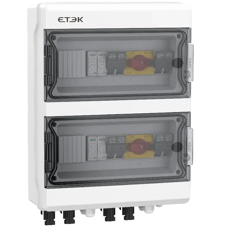
Even when the inverter has internal surge protection, external coordination at the combiner level typically reduces stress on the inverter’s input stage and can make maintenance more modular.
2) DC input of the inverter
The inverter is both expensive and sensitive. When the DC cables are longer than you would like, the inverter-side SPD can serve as a second protective stage. In larger systems, you might coordinate protection at both ends of a long run—array side/combiner side and inverter side—depending on cable length, installation class, and lightning exposure.
3) Grounding and bonding path quality
Surge protection is only as effective as the path to earth. A DC SPD does not “absorb” surges; it diverts energy. If the earthing conductor is long, thin, looped, or routed in a way that adds inductance, the protective action becomes slower and the residual voltage at the protected terminals rises.
That is why layout is not a cosmetic detail. It is part of the electrical design.
How a DC SPD protects equipment
A DC SPD is designed to react when voltage exceeds a threshold, temporarily creating a controlled low-impedance path to divert surge current away from sensitive components. In practical terms, it limits the transient overvoltage seen by your inverter input, MPPT stage, DC/DC converters, meters, and monitoring devices.
On the PV side, you will commonly see SPDs described by their installation class (often “Type 2” for many PV distribution points, and “Type 1+2” where direct lightning current may be present or where the building has an external lightning protection system and coordination is required).
From a system designer’s view, what matters is not only the SPD type, but the coordination story: the SPD’s maximum continuous operating voltage, its discharge capability, its voltage protection level, and how it is installed relative to the conductor geometry and the grounding system.
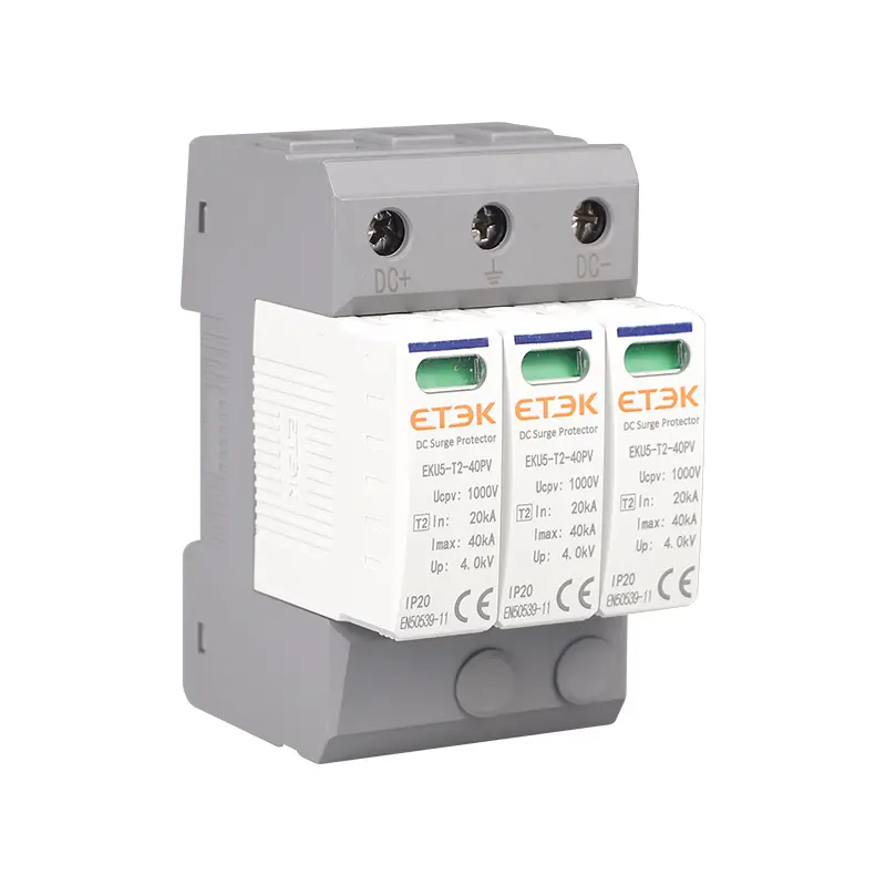
Here is a concrete example of a PV-oriented DC SPD option used in high-voltage arrays:
When surge energy is frequent (industrial switching environments, exposed locations, or sites with repeated thunderstorms), status indication and replacement strategy matter too. A well-specified SPD is not only about “bigger kA.” It is about consistent protection over time.
Selection checklist (without the jargon)
Datasheets are necessary, but selection decisions usually come down to a few questions. The list below is deliberately practical; it can be used for rooftop systems and for larger string inverter sites.
1) What is your maximum DC operating voltage?
Start from the array design: number of modules per string, module Voc at lowest temperature, and design safety margins. Your SPD’s maximum continuous operating voltage (often marked as Uc or similar) must be appropriate for the PV side voltage. Underrating here is a common cause of premature SPD ageing.
2) What is the likely surge environment?
If the site has external lightning protection, long rooftop conductors, or exposed field arrays, the surge environment is more severe. In these cases, coordination of SPD classes and placement becomes more important than simply choosing a single device at one point.
3) Where will you install it—combiner, inverter, or both?
Protection is a system, not a component. If the array-to-inverter distance is significant, you may need a staged approach: a DC SPD in the combiner box (close to string entry) and another stage near the inverter input. The objective is to keep the residual voltage low at the terminals that matter.
4) How will you coordinate with fuses, breakers, and disconnects?
On the PV DC side, protective coordination is often a small ecosystem: string fuses or DC breakers, a disconnect/isolator, and surge protection. The SPD needs a safe backup protection strategy (depending on the design) and a layout that avoids forcing surge current through unintended paths.
For readers who want to browse the product families involved in this ecosystem, these category pages provide a good starting point: PV combiner box solutions, AC/DC SPD lineup, and DC isolator switches.
Installation details that decide outcomes
Most surge-protection failures are not dramatic “device exploded” moments. More often, protection exists on paper but is weakened by installation decisions that are hard to spot after commissioning. If you only remember four details, make it these:
Keep earthing conductors short, direct, and low-inductance
The surge current is fast. Long, looping earthing conductors add inductance, which increases residual voltage at the protected terminals. Route the SPD-to-earth connection as short and straight as possible and avoid unnecessary bends.
Avoid large conductor loops between SPD and protected terminals
If the SPD connection forms a wide loop with the DC conductors, the loop area increases induced voltage during fast transients. In practice, a compact wiring geometry improves outcomes.
Match the installation point to the system architecture
For string inverter systems, combiner boxes often make surge protection serviceable and modular. For rooftop systems with short DC runs, a single coordinated point can be sufficient. For long runs, staged protection is frequently justified.
Plan inspection and replacement like any other maintenance item
Surge events accumulate. Where the SPD provides a status indicator, incorporate it into periodic inspection. Where replacement cartridges are used, keep spares and define the replacement trigger conditions.
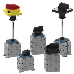
There is a related component that is easy to overlook: the DC isolator. It is the operator’s “safe separation” tool, especially during troubleshooting. A modern isolator series with PV-focused design considerations can be part of the reliability story, not just compliance.
ETEK PV protection building blocks
One reason PV protection projects become complicated is that they mix many small devices that must work together: string protection, switching, surge diversion, and enclosure design. When these elements are selected from compatible families and assembled in a clean architecture, the result feels straightforward in the field.
DC SPD for PV arrays
ETEK provides PV-oriented DC SPD options designed for high-voltage DC applications. If you are designing around modern arrays, focus on ratings that align with your string voltage and a protection level that respects sensitive inverter inputs. Start from the family overview at AC/DC SPD and then choose a configuration that matches the installation class and voltage.
PV combiner boxes for modular protection
A combiner box is not only a wiring convenience; it is a protective boundary. Good combiner designs reduce installation time, support clear labeling, and make string-level maintenance practical. Explore available configurations at Combiner Box, including options with DC fuses, DC MCB, isolators, and integrated SPDs.
DC isolator switches for safe maintenance
PV systems are maintained for decades, not months. A dependable disconnect strategy matters. ETEK’s isolator family includes panel-mount and enclosure solutions, as well as newer series intended for robust isolation. Browse the range at DC Isolator Switch.
Complementary DC protection
Depending on your array architecture, you may also coordinate with DC breakers and fuses. For reference, the PV distribution entry pages include DC circuit breaker and DC fuse families.
FAQ
Do I need a DC SPD if my inverter already has surge protection?
Internal protection may exist, but external coordinated protection can reduce stress and improve serviceability. In many designs, a combiner-box SPD stage helps manage surges before they reach the inverter’s input stage.
Is “higher kA” always better?
Not by itself. Discharge ratings matter, but correct voltage rating, low-inductance installation, and proper grounding often decide real protection quality. Oversizing without coordination can still leave you with high residual voltages at the terminals you care about.
Where should I place SPDs in a long-cable installation?
If the array-to-inverter DC cable run is long, staged protection (combiner side and inverter side) is frequently considered, especially in exposed locations. The final design should follow the site’s lightning risk assessment and applicable electrical codes.
What does a “Type 1+2” SPD mean for PV projects?
It typically indicates the SPD is designed to handle more severe surge conditions and can be used where lightning current protection and overvoltage protection need coordination. Always match the selection to installation standards and system architecture.
How do I keep surge protection effective over time?
Choose devices with clear status indication where possible, keep installation geometry compact, and include inspection in routine PV maintenance. Treat surge protection as a maintainable subsystem, not a one-time component.