EV Charger Protection Devices: RCD, SPD & Breaker Guide
If you’re specifying or installing EVSE, choosing the right EV charger protection devices is the difference between stable operation and repeated call-backs. EV charging stations combine continuous high current, sensitive electronics, and real-world exposure (outdoor cabinets, long feeder runs, switching events, lightning transients). If protection is underspecified, you’ll see nuisance trips, damaged control boards, burnt contactors, or—in the worst case—unsafe fault conditions.
- Key takeaway #1: EV circuits need the right residual-current strategy (Type B, or Type A + 6mA DC detection).
- Key takeaway #2: Layered SPD placement is critical for outdoor/public EVSE and long cable runs.
- Key takeaway #3: Breaker sizing should reflect continuous load and coordination with SPD backup protection.
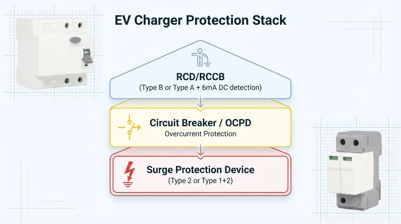
This guide explains how to choose and coordinate the three core protection layers for AC EV chargers and many EVSE installations: RCD/RCCB (residual current protection), OCPD (MCB/RCBO for overcurrent), and SPD (surge protection). You’ll also get an installer-ready checklist and a simple selection map for common 7.4kW/11kW/22kW projects.
For product-level references and EV categories, start here: ETEK EV Charging Station.
1) Standards snapshot: what the EVSE rules focus on
Most EV charging discussions mix three different “protection” problems:
- Electric shock protection: managing AC residual current, pulsed DC, and smooth DC leakage created by the vehicle’s AC/DC conversion stage.
- Overcurrent/short-circuit protection: cable protection, breaker coordination, and ensuring the circuit is sized for continuous load.
- Transient overvoltage protection: lightning/switching surges that can destroy EVSE electronics or degrade insulation.
IEC guidance for EV charging installations is widely referenced in industry education material. For example, the Electrical Installation Guide wiki summarizes that EV charging installations are covered by IEC 60364-7-722, and highlights dedicated circuits, 30mA RCD protection, and DC fault current measures (Type B or Type A/F + RDC-DD 6mA). It also discusses surge protection for publicly accessible EVSE and references installing SPDs complying with IEC 61643-11.
2) RCD selection: Type B vs Type A + 6mA DC detection
EV chargers can generate DC leakage current. If you use the wrong residual-current protection upstream, you risk either nuisance tripping (poor availability) or blinding/desensitization of upstream RCDs (a safety risk).
| Option | What it is | Typical use case | Pros | Trade-offs |
|---|---|---|---|---|
| Type B RCD/RCCB | Residual-current device designed to trip correctly with AC + pulsed DC + smooth DC components. | Installations where you want robust DC leakage handling and simpler external architecture. | Strong compatibility with EV leakage behaviors; often the simplest external solution. | Typically higher cost; selection and coordination still matter. |
| Type A RCD + 6mA DC detection (RDC-DD) | Type A RCD combined with a 6mA residual DC detecting device compliant with IEC 62955 (often inside the EVSE). | EV chargers with integrated 6mA DC detection, or projects specifying A + 6mA architecture. | Common approach for modern EVSE; can be cost-effective. | Design must be explicit about where DC detection is implemented to avoid nuisance trips and confusion during inspection. |
ETEK offers EV-focused residual-current protection options you can map into either approach:
3) SPD selection: Type 2 vs Type 1+2, where to install, and why distance matters
EV chargers contain power electronics and control boards that are vulnerable to transient overvoltages. Surges can come from lightning (direct or indirect), utility switching, or large local loads.
Schneider Electric describes an SPD as a device connected in parallel that limits transient overvoltage and diverts peak voltage to earth, and outlines Type 1 / Type 2 / Type 3 roles for low-voltage installations. NEMA defines SPDs as devices that limit transient voltages by diverting or limiting surge current and repeating these functions.
ETEK’s SPD portfolio overview references AC and EV charging station applications and includes Type 1+2 and Type 2 devices: ETEK Surge Protection Device.
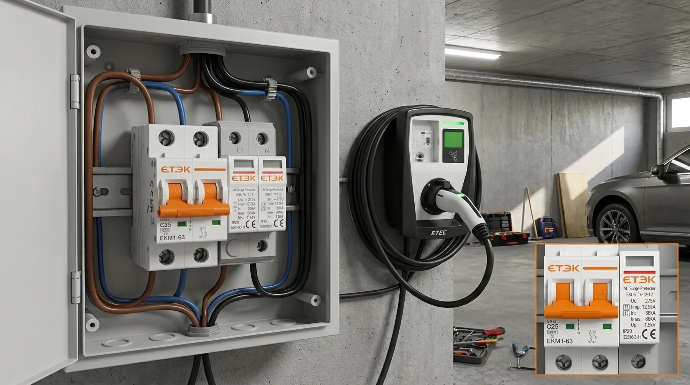
Where to install SPDs in EV charging projects
- Main distribution board: Typically a Type 2 SPD for many installations; if the site has an external lightning protection system (LPS), consider Type 1+2 at the service entrance.
- At or inside the EVSE cabinet: Add another SPD when the feeder run is long (long cables can increase surge stress at the EVSE).
- Near sensitive electronics: Type 3 (point-of-use) can be used downstream of Type 2 where appropriate.
What to check on the SPD datasheet
- System voltage & wiring system: 230/400V AC, TT/TN/IT, single-phase vs three-phase.
- SPD type/class: Type 2 for distribution boards; Type 1+2 where lightning current capability is needed.
- Protection level (Up): lower Up generally means better residual voltage limitation for electronics.
- Coordination / backup protection: confirm recommended fuse/MCB coordination from the manufacturer.
4) Breaker/OCPD selection: sizing, coordination, and typical examples
EVSE is typically a continuous load. Size conductors and breakers to handle sustained current, and confirm the charger’s maximum configured current is controlled (often locked by key/tool).
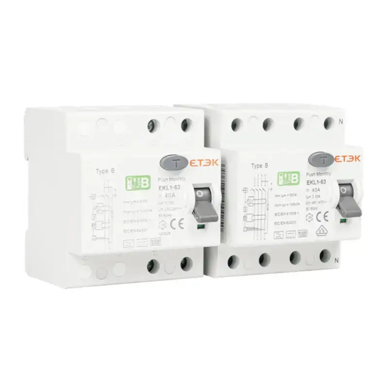
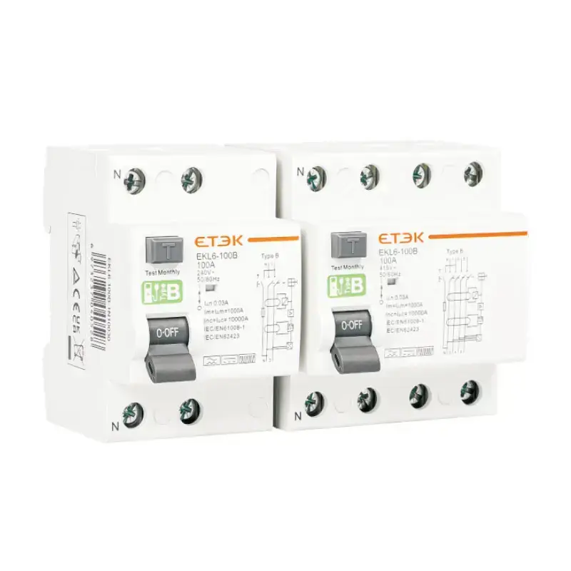
ETEK’s EV-focused Type B RCCB page lists common installer configurations for 3.7kW / 7.3kW / 11kW / 22kW projects, which is useful as a starting reference: EKL1-63B.
Coordination note: don’t forget SPD backup protection/coordination requirements (many manufacturers publish a coordination table).
5) Quick solution map for common EV charger scenarios
Scenario A: Residential / small commercial wallbox (short cable run)
- Residual current: Type A + 6mA DC detection (built-in or upstream) OR Type B, depending on spec and selectivity goals.
- Overcurrent: appropriately sized MCB/RCBO for the configured current.
- Surge: Type 2 SPD at main board; add near EVSE if the run is long or environment is harsh.
Scenario B: Public access AC chargers (parking lots, retail, fleets)
- Residual current: prioritize robust DC leakage handling and avoid upstream RCD blinding through correct architecture.
- Surge: plan layered SPD protection at feeding board and near/inside EVSE.
- Earthing/bonding: verify equipotential bonding early (it affects both safety and SPD performance).
Scenario C: Multi-charger sites (several EVSE in parallel)
- Load management: consider an LMS to avoid oversizing and peak-demand issues.
- Selectivity: design so one fault doesn’t trip all chargers.
- Surge segmentation: use layered SPD strategy to protect both feeders and electronics.
6) Commissioning checklist (practical)
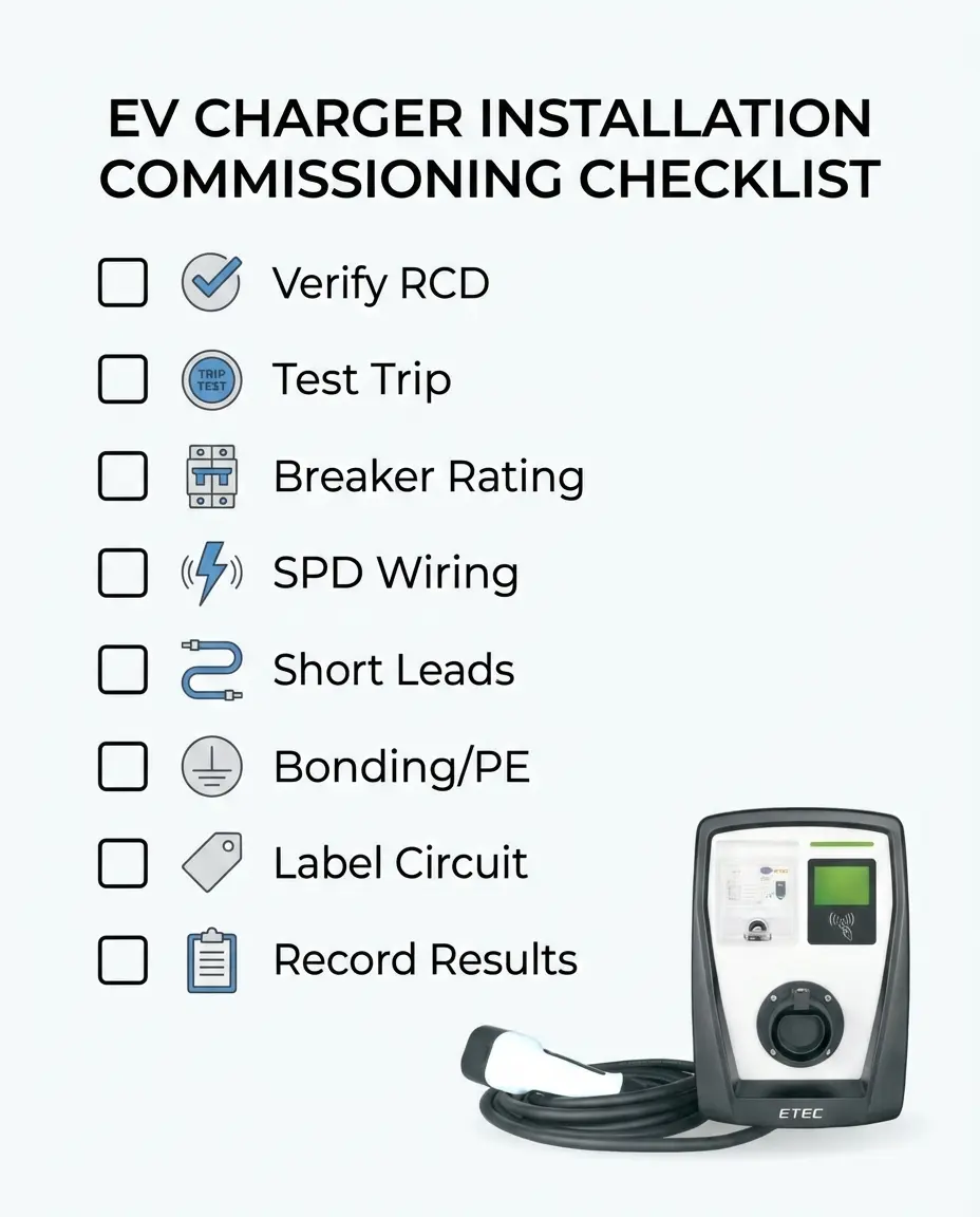
- Confirm charger configuration: max current, phases, and whether current limit is locked by tool/key.
- Verify RCD architecture: Type B vs Type A + 6mA DC detection; confirm whether the EVSE already provides internal 6mA DC detection.
- Test RCD function: trip test and labeling; ensure correct disconnection behavior for your chosen device type.
- Verify breaker rating: correct In and breaking capacity for the panel’s prospective short-circuit current.
- Check SPD wiring: short leads, correct PE bonding, correct SPD type (Type 2 vs Type 1+2), correct placement.
- Grounding & bonding: confirm continuity and bonding for metallic EVSE structures and nearby conductive parts.
- Record baseline: RCD test results, SPD status indicators, and key electrical measurements per local practice.
7) FAQ
Do EV chargers require Type B RCD?
Not always. Many compliant architectures exist, including Type A combined with 6mA DC detection (RDC-DD) per IEC 62955. Type B is often selected when you want robust tolerance to DC leakage behaviors and a simpler external architecture. Always verify what the EVSE already integrates.
Where should I place the SPD for an EV charging station?
Start at the feeding distribution board (often Type 2). For long cable runs or outdoor/public-access EVSE, add layered protection closer to the EVSE. Also verify SPD coordination requirements (backup fuse/MCB) and keep lead lengths short.
What’s the difference between Type 1, Type 2, and Type 3 SPD?
Common guidance describes Type 1 for service entrance / lightning current environments, Type 2 for downstream distribution boards, and Type 3 for point-of-use near sensitive loads (typically downstream of Type 2).
8) Next steps: get a protection BOM that matches your charger
Send your charger model, rated power (7.4kW/11kW/22kW), supply system (TT/TN), and cable run length. We can propose a practical protection BOM (RCD + breaker + SPD) and wiring/commissioning notes.
ETEK EV charging protection references:
- ETEK: EKL1-63B Type B RCCB for EV charging
- ETEK: EKL6-63EV Type A + DC6mA EV RCD
- ETEK: Surge Protection Device overview
Sources
- Electrical Installation Guide: EV charging – electrical installation design
- DEHN: Relevant standards for e-mobility
- Schneider Electric FAQ: What is an SPD and how does it work?
- NEMA Surge Protection Institute: What are SPDs?
- ETEK: EKL1-63B Type B RCCB for EV charging
- ETEK: EKL6-63EV Type A + DC6mA EV RCD
- ETEK: Surge Protection Device overview